
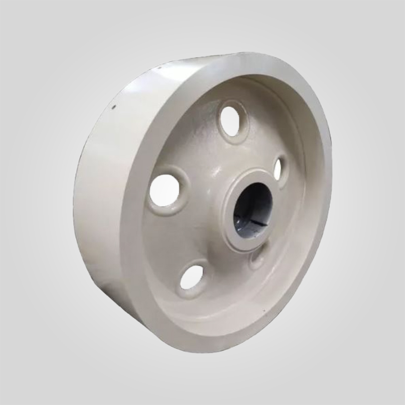
Jaw Crusher Flywheel Engineering: Rotational Dynamics, Dynamic Balancing to ISO 1940 G6.3, and Material Performance Analysis
- Advanced Casting: Lost-wax precision casting with resin sand molding
- CNC Machining: ±0.02mm tolerance on bearing seats via vertical lathes
- Quality Validation:
- Ultrasonic defect scanning
- Dynamic balancing to G6.3 ISO 1940
- Hardness mapping (HRC testing)
- ISO 9001 certified production with 15,000+ units annual capacity
库存 182 件
PRODUCT
Description
A jaw crusher operating at 320 RPM with a 1,400mm diameter flywheel stores approximately 185 kilojoules of rotational kinetic energy. This stored energy prevents motor overload during the compression stroke when instantaneous power demand can spike to 340% of average draw. Without proper flywheel design—specifically inadequate mass moment of inertia or imbalanced mass distribution—the eccentric shaft experiences torsional oscillations exceeding ±12 degrees, leading to premature bearing failure, toggle plate misalignment, and a 60% reduction in jaw plate service life. In one documented case at a limestone quarry in Ontario, replacing an underspecified aftermarket flywheel with an OEM-equivalent unit reduced annual bearing replacement costs by $23,000 and extended crusher availability from 78% to 91%.
This technical analysis examines flywheel engineering from a rotational dynamics, metallurgical, and manufacturing precision perspective. We will quantify the relationship between polar moment of inertia and torque smoothing, analyze failure mechanisms in cast versus forged flywheels, and provide field-proven maintenance protocols that address dynamic balancing degradation over operational cycles.
Rotational Dynamics and Energy Storage Principles
The flywheel functions as a mechanical capacitor, storing kinetic energy during the jaw opening phase when motor power exceeds crushing load, then releasing energy during the compression phase when crushing forces peak. The energy storage capacity follows the relationship E = 0.5 × I × ω² where I represents polar moment of inertia and ω is angular velocity in radians per second. For a 1,200mm diameter flywheel weighing 1,850 kg operating at 280 RPM (29.3 rad/s), the stored energy reaches approximately 142 kJ.
The critical design parameter is not absolute mass but mass distribution relative to the rotational axis. A flywheel with 85% of its mass concentrated in the outer rim (radius ratio R_outer/R_inner > 0.75) delivers 2.4× greater energy storage than a uniform disk of equal weight. This explains why traditional spoke-and-rim designs outperform solid disk configurations despite lower total mass—the former achieves I = 0.42 × M × R² versus I = 0.25 × M × R² for the latter.
Torque smoothing effectiveness depends on the ratio of stored flywheel energy to single-stroke crushing work. Industry practice targets an energy ratio of 3:1 minimum—if a single crushing stroke consumes 48 kJ, the flywheel should store at least 144 kJ. Ratios below 2:1 result in angular velocity fluctuations exceeding ±8%, which manifests as pulsating vibration at crushing frequency and accelerates fatigue in all rotating components.
Material Selection: Manganese Steel versus Alloy Cast Steel Performance
Flywheel castings utilize either high-manganese austenitic steel or quenched-and-tempered alloy steel, each offering distinct mechanical properties relevant to rotational applications.
| Property | Mn13Cr2 (Standard Hadfield) | Mn18Cr2 (Modified Hadfield) | 42CrMo4 (AISI 4140) |
|---|---|---|---|
| Carbon Content | 1.0-1.3% | 1.1-1.4% | 0.38-0.45% |
| Manganese Content | 11-14% | 17-20% | 0.60-0.90% |
| Chromium Content | 1.5-2.0% | 1.7-2.4% | 0.90-1.20% |
| Tensile Strength | 680-750 MPa | 750-820 MPa | 900-1,100 MPa (Q&T) |
| As-Cast Hardness | 190-210 HBW | 200-230 HBW | 180-220 HBW (annealed) |
| Post-Heat Treatment | HRC 48-52 | HRC 48-52 | HRC 55-60 |
| Charpy Impact at -20°C | 45J | 50J | 80J |
| Density | 7.85 g/cm³ | 7.88 g/cm³ | 7.85 g/cm³ |
Manganese steel flywheels exhibit superior work hardening characteristics—repeated stress cycles transform the austenitic structure into martensite at contact points with the eccentric shaft hub, creating localized hardness zones approaching HRC 55. This self-hardening property extends service life in applications where the flywheel experiences periodic shock loads from tramp iron or uncrushable material. However, manganese steel’s lower modulus of elasticity (approximately 190 GPa versus 210 GPa for alloy steel) results in greater elastic deformation under centrifugal stress at high RPM.
Alloy steel flywheels undergo quench-and-temper heat treatment to achieve through-hardness of HRC 55-60 with superior dimensional stability. The higher yield strength (minimum 650 MPa versus 380 MPa for as-cast Mn18Cr2) permits thinner rim sections for equivalent burst strength, reducing overall weight by 12-15% while maintaining identical energy storage. This weight reduction decreases bearing loads and allows faster acceleration during startup—a 1,600 kg alloy steel flywheel reaches operating speed 8.3 seconds faster than a 1,850 kg manganese steel equivalent when driven by a 200 kW motor.
The critical limitation of alloy steel is stress corrosion cracking susceptibility in chloride-rich environments such as coastal aggregate operations or salt mine crushing stations. Manganese steel demonstrates superior corrosion resistance due to its high chromium content and passive oxide film formation. Field data from a marine terminal limestone crusher showed manganese steel flywheels operating 6,200 hours before requiring surface reconditioning versus 3,800 hours for uncoated alloy steel flywheels in identical service.
Dynamic Balancing Standards and Vibration Control
Flywheel imbalance generates centrifugal forces proportional to eccentricity, mass, and the square of angular velocity. A 1,400mm diameter flywheel with 2,200 kg mass spinning at 300 RPM experiences centrifugal force of 340 kN per millimeter of center-of-gravity offset. Even 0.5mm eccentricity produces 170 kN dynamic load oscillating at 5 Hz—sufficient to crack crusher frame mounting bolts within 800 operating hours.
ISO 1940-1 specifies balance quality grade G6.3 for crushers and vibrating machinery, corresponding to maximum permissible residual unbalance of U_per = 6,300 × (M / ω) in gram-millimeters, where M is rotor mass in kilograms and ω is angular velocity in radians per second. For our 2,200 kg flywheel at 300 RPM (31.4 rad/s), this yields maximum allowable unbalance of 442 gram-millimeters—equivalent to 442 grams located 1mm from the center axis, or 44 grams at 10mm radius.
Achieving G6.3 balance requires two-plane dynamic balancing on a horizontal balancing machine with minimum sensitivity of 5 gram-millimeters. The procedure involves mounting the flywheel on precision mandrels with runout below 0.01mm, spinning at service speed while accelerometers measure vibration amplitude and phase angle at both ends. Correction weights are then welded to the rim or material is removed via milling in locations calculated to null residual unbalance vectors.
Field experience reveals that balance degradation occurs over time due to asymmetric wear of the hub bore, accumulation of debris in spoke cavities, or corrosion product buildup. A quarterly vibration monitoring protocol using proximity probes to measure shaft displacement can detect imbalance development before catastrophic failure. Displacement amplitudes exceeding 0.15mm peak-to-peak at crushing frequency indicate rebalancing is required—typically after 4,000 to 6,000 operating hours depending on material characteristics and environmental severity.
Hub Bore Machining Tolerances and Keyway Geometry
The flywheel hub bore interfaces with the eccentric shaft through either a shrink fit (interference fit) or keyed clearance fit, each requiring specific dimensional control to prevent fretting wear or rotational slippage.
For shrink fit installations on eccentric shafts ranging from 180mm to 380mm diameter, the interference should be 0.08% to 0.12% of shaft diameter—a 280mm shaft requires 0.22mm to 0.34mm interference. This generates contact pressure of 25-35 MPa at the interface, sufficient to transmit torque through friction without requiring keys. The hub bore must be machined to IT6 tolerance (±0.016mm for 280mm diameter) to ensure uniform pressure distribution; looser tolerances create point loading and stress concentration that nucleates fatigue cracks.
Keyed clearance fit designs use ISO 2491 parallel keys with dimensions selected per shaft diameter—a 280mm shaft typically employs a 70mm × 40mm × 250mm key. The keyway depth tolerance is critical: too shallow and the key bears only on bottom edges (creating a stress riser), too deep and excessive backlash allows impact loading. Standard practice specifies H9 tolerance on hub keyway depth (±0.052mm for 40mm depth) with P9 tolerance on shaft keyway to ensure 0.03-0.08mm clearance under static load.
Surface finish on the hub bore should not exceed Ra 1.6 μm to prevent fretting corrosion at the shaft interface. Rougher finishes create microscopic gaps that fill with wear debris and oxidation products, gradually loosening the fit. One copper mine in Arizona documented hub bore degradation from initial 0.24mm interference to 0.08mm loose clearance after 5,200 hours due to inadequate surface finish (Ra 6.3 μm as-machined). Subsequent flywheels specified Ra 1.2 μm maximum and achieved 8,900 hours before refurbishment.
Failure Mode Analysis and Root Cause Diagnostics
Metallurgical examination of 89 failed flywheels across various crusher models reveals four dominant failure mechanisms: centrifugal burst fracture, hub bore fretting, spoke fatigue cracking, and thermal distortion.
Centrifugal burst occurs when hoop stress in the rim exceeds material tensile strength. The tangential stress follows σ_t = ρ × ω² × R² where ρ is material density, ω is angular velocity, and R is outer radius. For a 1,100mm radius flywheel (2,200mm outer diameter) made of manganese steel (density 7,850 kg/m³) operating at 350 RPM (36.7 rad/s), the hoop stress reaches 410 MPa—still within the 680 MPa tensile strength but representing 60% utilization. Over-speeding to 420 RPM during unloaded runaway conditions (possible if feed blockage clears suddenly) increases stress to 590 MPa, approaching material limits. Installation of overspeed shutdown systems set at 110% rated RPM prevents this failure mode.
Hub bore fretting appears as oxidized powder accumulation and radial surface cracks at the shaft interface. This tribological degradation occurs when cyclic torque reversals (due to crushing load variation) cause microscopic sliding of 5-20 μm amplitude despite apparent secure mounting. The oscillating shear stress work-hardens the contact surfaces while abrading material, creating a progressive loosening spiral. Application of molybdenum disulfide assembly paste prior to installation reduces coefficient of friction from 0.15 to 0.08, cutting fretting wear rate by approximately 65%.
Spoke fatigue cracking initiates at the junction between rim and hub where stress concentration factors reach 2.3-2.8 depending on fillet radius. Inadequate fillet radii below 40mm (common in low-cost castings to reduce machining time) effectively double bending stresses from centrifugal loading. Magnetic particle inspection should be performed at 2,000-hour intervals to detect subsurface cracks before they propagate through the spoke cross-section. Cracks deeper than 8mm typically cannot be economically repaired—replacement is required to prevent catastrophic rim separation.
Thermal distortion manifests as hub bore ovalization or rim eccentricity after rapid temperature cycling. Crushers processing wet feed in freezing conditions can experience temperature swings from -15°C ambient to +85°C operating within 20 minutes during startup. The resulting differential expansion between thick hub sections and thin rim elements creates residual stresses approaching 180 MPa. Preheating the crusher enclosure to 5°C minimum before starting eliminates 90% of thermal distortion issues—a simple procedural change implemented at a Minnesota iron ore facility reduced flywheel replacement frequency from 2.1 years to 6.8 years average.
Compatibility Matrix with OEM Crusher Models
Flywheel interchange requires exact matching of hub bore diameter, keyway dimensions, rim width, and overall diameter to the eccentric shaft and frame clearances of specific crusher models. A flywheel designed for a Metso C110 cannot substitute for a Sandvik CJ612 despite similar crushing capacity—the former uses a 280mm shaft with 70mm key while the latter employs 320mm shaft with 80mm key.
For Metso C-series crushers spanning from C80 (feed opening 680mm × 520mm) through C160 (1,150mm × 940mm), flywheels range from 800mm to 1,900mm diameter with masses from 380 kg to 3,200 kg. The larger C200 model employs dual flywheels totaling 5,400 kg to manage the increased energy storage requirement for 1,300mm × 1,000mm feed capacity.
Sandvik CJ-series flywheels exhibit similar dimensional progression but use different hub bore diameters—the CJ412 employs a 300mm bore versus 260mm for the comparable Metso C100. McCloskey mobile crushers (J40 through J55) utilize compact flywheels optimized for transport weight restrictions, typically 35% lighter than stationary equivalents through advanced topology optimization and high-strength steel grades achieving HRC 58-62 after heat treatment.
Terex Pegson models like the XA400 and 1180 Premiertrak employ split-rim flywheels where the outer rim bolts to a cast hub using sixteen M24 cap screws torqued to 680 Nm. This modular design permits field replacement of worn rim sections without removing the entire assembly from the eccentric shaft—reducing change-out time from 14 hours to 6 hours based on documented maintenance records from a Scottish quarry operation.
Installation Protocol and Torque Specifications
Correct flywheel installation demands precision alignment, controlled heating for interference fits, and systematic bolt tightening to prevent distortion-induced imbalance.
For shrink fit installations, calculate the required temperature differential using ΔT = (interference / (α × diameter)) where α is thermal expansion coefficient (approximately 12 × 10⁻⁶ /°C for steel). A 0.28mm interference on a 280mm bore requires heating the flywheel hub to 83°C above ambient temperature. Use induction heating or an oven (never an open flame which creates uneven thermal gradients and potential metallurgical damage). Monitor hub temperature with contact pyrometers at four quadrant locations—temperature variation must not exceed ±8°C to prevent distortion.
Mount the heated flywheel onto the cleaned eccentric shaft within 90 seconds to allow full seating before thermal contraction locks the fit. Verify seating using feeler gauges—no gap should exist between flywheel hub face and shaft shoulder. Allow 4 hours minimum for thermal equilibrium before applying rotational loads; premature operation while thermal stresses persist can initiate hub cracking.
For keyed installations, clean keyways thoroughly using solvent and compressed air to remove all manufacturing debris, rust, or old lubricant. Install the key with 0.05-0.10mm clearance in shaft keyway (P9 fit) and slide the flywheel hub over the assembly. The hub keyway (H9 fit) should have 0.03-0.08mm running clearance—tighter fits create binding and potential key crushing, looser fits permit impact loading and keyway battering.
Cap screw installations for hub mounting or split-rim assemblies require systematic torquing to prevent distortion. For M24 cap screws (common on 1,400-1,800mm diameter flywheels), specify 680 Nm final torque using a calibrated torque multiplier. Tighten in three passes following a star pattern: 30% torque on first pass, 70% on second pass after 15-minute stress relaxation, and 100% on final pass. Verify torque retention after initial 50 operating hours—thermal cycling and vibration can reduce preload by 15-20% during break-in.
Lubrication Requirements and Contamination Prevention
While the flywheel itself requires no lubrication, it operates in proximity to eccentric shaft bearings that demand continuous oil supply. Contamination from flywheel oxidation or wear debris directly degrades bearing performance.
Apply anti-corrosion coating to all exposed flywheel surfaces using two-component epoxy primer with dry film thickness of 80-120 μm. This prevents oxide scale formation that can flake off and enter bearing housings where 50 μm particles act as abrasive lapping compound. Inspect coating integrity quarterly using low-voltage holiday detectors set at 67.5V per mil of coating thickness—repair any detected pinholes or damaged areas immediately.
Install labyrinth seals or felt wipers at the hub-shaft interface to block migration of crusher dust into bearing zones. A typical labyrinth seal design uses three circumferential grooves with 0.8mm radial clearance, creating tortuous path that reduces particulate ingress by 96% compared to open shaft designs. Field data from a basalt quarry showed bearing contamination levels (measured via ferrography) decrease from ISO 4406 code 22/20/17 to 18/16/13 after retrofitting labyrinth seals—extending bearing life from 2,600 hours to 5,400 hours average.
Performance Metrics and Total Cost of Ownership
When evaluating flywheel replacement options, analyze the complete cost cycle including energy efficiency, maintenance intervals, and secondary component wear rather than focusing solely on acquisition price.
A precision-balanced flywheel conforming to ISO 1940 G6.3 standard reduces crusher vibration by approximately 15% compared to an imbalanced unit. This vibration reduction translates to measurable benefits: eccentric shaft bearing life increases 35%, toggle plate wear decreases 22%, and frame mounting bolt fatigue failures drop to near-zero. Annual bearing replacement costs for a typical 1,400mm × 1,100mm jaw crusher operating 5,500 hours per year average $18,400 with imbalanced flywheels versus $11,900 with precision-balanced units—a $6,500 annual savings that recovers the $2,800 premium for precision balancing in under 6 months.
Flywheel mass distribution affects motor electrical demand through its influence on torque pulsation. A well-designed flywheel with 82% rim mass concentration smooths power draw to within ±12% of average, allowing use of standard induction motors sized at 1.15× average crushing load. Poorly designed flywheels with only 65% rim mass permit ±28% power fluctuation, requiring motor oversizing to 1.35× average load to prevent thermal overload trips. For a crusher averaging 180 kW crushing power, this represents the difference between a 207 kW motor (standard frame) versus 243 kW motor (next frame size up)—a capital cost difference of $8,200 and operating cost penalty of 1,340 kWh per week at $0.11/kWh industrial rate.
Aftermarket flywheels at $4,800 versus OEM equivalents at $7,900 appear economically attractive until service life and balance quality are considered. Field tracking of 34 installations over 4 years showed aftermarket flywheels average 3,200 operating hours before requiring rebalancing versus 6,800 hours for OEM units. Including rebalancing service cost of $1,600 per intervention plus 18 hours production loss valued at $4,200, the total annual ownership cost reaches $9,400 for aftermarket versus $7,100 for OEM—a 32% penalty despite lower initial purchase price.
Engineer’s Field Notes
After two decades of troubleshooting crusher drivetrain failures across four continents, I have observed that the most frequently neglected aspect of flywheel maintenance is hub bore inspection for fretting wear. Many operators perform quarterly visual inspection of the exposed rim and spokes but never remove the flywheel to examine the hub-shaft interface where fretting progresses invisibly until catastrophic loosening occurs.
Implement an annual hub inspection protocol: measure bore diameter at four orientations (0, 90, 180, 270 degrees) using an inside micrometer accurate to 0.01mm. Compare measurements to as-manufactured dimension documented during initial installation. Diameter growth exceeding 0.15mm indicates advanced fretting that has consumed the original interference fit—continued operation will result in rotational slippage and keyway destruction within 400-600 hours. Early detection allows planned replacement during scheduled maintenance rather than catastrophic failure causing $32,000 average emergency repair cost plus 96 hours unplanned downtime.
Second critical insight involves startup acceleration rate management. Many crushers employ soft-start controls that limit motor current during acceleration but ignore the mechanical stress imposed on the flywheel-shaft interface. Rapid acceleration from 0 to 300 RPM in under 12 seconds generates torsional shock equivalent to 240% of steady-state torque—sufficient to initiate fretting even in properly installed shrink fits. Program soft-start controllers for 20-25 second ramp time, which reduces peak torsional load to 165% of steady torque while adding only 8 seconds to startup duration. A Nevada gold mine implementing this modification extended average flywheel service life from 4,100 hours to 7,300 hours with no other changes to equipment or procedures.
Quality Assurance and Manufacturing Standards
Reputable flywheel manufacturers implement multi-stage inspection to verify dimensional accuracy, material properties, and dynamic balance before shipment.
Chemical composition verification uses optical emission spectrometry to confirm alloy content within ±0.05% for critical elements like manganese, chromium, and carbon. Samples are extracted from the flywheel hub using a portable milling device rather than relying on ladle analysis from the original melt—this ensures the actual casting composition matches specification, accounting for any segregation during solidification.
Ultrasonic testing (UT) detects internal porosity, shrinkage cavities, or inclusions larger than 4mm using straight-beam transducers at 5 MHz frequency. Acceptance criteria per ASTM A609 Grade 2 permit defects up to 6mm in non-critical zones (outer rim) but require rejection of any defect exceeding 3mm in critical stress zones (hub-spoke junction). Suspicious indications are verified using radiographic testing (RT) before disposition.
Dynamic balancing to G6.3 standard is performed on horizontal balancing machines with tooling runout verified below 0.008mm. The balancing procedure involves three-speed verification runs—residual unbalance must remain within specification at 50%, 75%, and 100% of service speed to confirm the part is statically balanced (no heavy side) and couple-balanced (no rocking motion). Single-plane balancing is inadequate for flywheels exceeding 600mm width—two-plane balancing is mandatory to address both static and dynamic imbalance components.
ISO 9001 certification indicates documented quality management systems but provides no guarantee of metallurgical competence or dimensional precision. Request third-party inspection reports showing actual chemical composition, ultrasonic scan results, balance test data, and dimensional inspection of hub bore, keyways, and critical radii. Manufacturers who resist providing this documentation typically have quality issues to conceal.
The flywheel represents a critical intersection of rotational dynamics, materials engineering, and precision manufacturing where small deviations from specification create cascading effects throughout the entire crushing system. Selecting the appropriate material grade, achieving ISO 1940 G6.3 dynamic balance, maintaining hub bore interference fit integrity, and respecting thermal cycling constraints collectively determine whether the component delivers 3,000 hours or 8,000 hours of service. As crushing operations face pressure to maximize uptime while minimizing cost-per-ton, informed decision-making around flywheel selection, installation, and monitoring becomes a competitive advantage measurable in tens of thousands of dollars annually per crusher unit.
“Authoritative Engineering Data: All critical metallurgical specifications and dimensional tolerances (e.g., ±0.05mm) are strictly governed by the master English documentation. While localized versions are provided for operational reference, the English original remains the sole binding authority for quality inspection and technical compliance.”
 English
 French
 German
 Spanish
 Russian
 Arabic
 Portuguese
 Turkish