

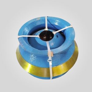
Sandvik CH660 Top Shell | OEM Ref: 452.3760-001 | ASTM A148 Cast Steel
OEM Part Number :452.3760-001 (Alternate ID: 213693)
Compatible Crusher Models: Sandvik CH660, H6800, H6000 Hydrocone®
Manufacturing Standard: OEM-Compatible Specifications
Design Features: Unibody Mainframe, Top-Loading Design, Integrated Spider Arm Shields and Pipework
System Compatibility :Hydroset™ System, ASRi™ Automated Control System
Compatible Chamber Types: EF, F, MF, M, MC, C, CX, HR
Availability: Ex-Stock, Supplied with Transport Frame
库存 32 件
PRODUCT
Description
| Technical Parameter | Specification Value | Engineering Standard / Note |
|---|---|---|
| OEM Part Number | 452.3760-001 (Alt: 213693) | Sandvik CH660 / H6800 / H6000 |
| Component Type | Unibody Top Shell (Integrated Spider) | Single-piece Casting Design |
| Material Grade | ASTM A148 Grade 80-50 (or equivalent GS-20Mn5) | High-Strength Structural Cast Steel |
| Tensile Strength (Rm) | ≥ 550 MPa (80,000 psi) | ASTM A370 Standard |
| Yield Strength (Re) | ≥ 345 MPa (50,000 psi) | Critical for Load Resistance |
| Impact Toughness | ≥ 27 J @ -20°C | Charpy V-Notch (Low Temp Ductility) |
| Weight (Approx) | 12,500 kg – 14,000 kg | Requires Heavy Lift Protocol |
| Machining Tolerance | Spider Bore Concentricity: 0.05mm | Relative to Bottom Flange Datum |
| NDT Protocol | Magnetic Particle (MT) + Ultrasonic (UT) | ASTM E709 / ASTM A609 Level 2 |
| Surface Finish (Mating) | Ra 3.2μm (Flange) | Ensures rigid joint with Bottom Shell |
Technical Highlights: Structural Metallurgy, Unibody Casting, and Precision Geometry
The Top Shell (452.3760-001) for the Sandvik CH660 (formerly Svedala H6800) is not merely a cover; it is the static reaction frame of the crusher. In the Hydrocone design, the Top Shell integrates the “Spider” assembly—the central hub that supports the top of the main shaft. This unibody design means the casting must handle complex multi-axial stresses: the vertical tension from the crushing force trying to lift the shell, the radial pressure from the rock crushing against the concaves, and the localized stress at the spider bearing.
The integrity of this 13-ton component is defined by the quality of the casting solidification and the precision of the machining relative to the crusher’s centerline.
1. Metallurgical Architecture: ASTM A148 Grade 80-50 Structural Cast Steel
Unlike wear parts (Manganese) or shafts (Forged Alloy), the Top Shell is manufactured from **High-Strength Structural Cast Steel**, typically **ASTM A148 Grade 80-50** (or European EN 10293 Grade GS-20Mn5). This material selection is a deliberate engineering trade-off between Weldability and Yield Strength.
- Weldability Factor: Top Shells operate in abrasive environments. The “Rock Box” effect on the spider arms means they will eventually wear. By using a low-to-medium carbon steel (C < 0.25%), we ensure the casting can be repaired via welding (using E7018 low-hydrogen electrodes) without requiring a complex post-weld heat treatment that would be impossible in the field.
- Shock Absorption (Ductility): The material must possess significant elongation (>18%) and impact toughness. When an uncrushable object (tramp iron) passes through the CH660, the accumulator relieves pressure, but the Top Shell absorbs the immediate shockwave. A brittle material (like excessive high-carbon steel) would suffer catastrophic brittle fracture at the spider arms.
2. The Unibody Spider Design: Solidification Simulation
The CH660 utilizes a “unibody” design where the spider arms are cast integrally with the outer shell. This eliminates bolted joints but complicates the foundry process.
- Hot Spot Management: The junction where the heavy spider arms meet the outer rim is a thermal “hot spot” during casting solidification. If cooling is not controlled, shrinkage porosity (voids) will form here. We utilize **MAGMAsoft** solidification simulation to design exothermic risers that feed molten metal into these junctions, ensuring a density >7.8 g/cm³ and an ASTM E446 Class 2 radiographic quality.
- Spider Hub Integrity: The central hub houses the Spider Bushing. This bore is the geometric “North Star” of the crusher. Our manufacturing process involves rough machining followed by a **Stress Relief Anneal at 600°C**. This releases residual casting stresses. Only then is the final boring performed. This prevents the bore from warping (going oval) after the component is put into service, ensuring the main shaft remains perfectly vertical.
3. Machining Precision: The Flange and Rim
The Top Shell mates with the Bottom Shell. This interface is critical.
- Flange Flatness: The bottom mating flange is machined to a flatness tolerance of **0.10mm over the entire diameter**. Any gap here leads to “fretting” (micromotion) between the top and bottom shells. Once fretting starts, the bolts lose tension, and the flange surfaces are destroyed.
- Concave Landing Surface: The internal taper where the Concave (Bowl Liner) sits is machined to **IT7** tolerances. This surface must be perfectly concentric to the Spider Hub bore. If it is eccentric, the CSS (Closed Side Setting) will vary around the chamber, causing uneven bearing wear and segregated product output.
Deep Dive: Failure Mechanics and Operational Stress Analysis
Understanding how a Top Shell fails allows for better maintenance planning. It is a fatigue-limited component, not an infinite-life part.
1. Spider Arm Erosion (The “Rock Box” Failure)
The spider arms are directly exposed to the feed material.
- Mechanism: While protected by Arm Liners, fine abrasive dust packs between the liner and the cast arm. Over years, this dust acts as grinding paste. Additionally, if liners are not replaced promptly, the rock flow erodes the structural steel of the arm.
- Critical Limit: If the spider arm thickness is reduced by >15% due to wear, the structural modulus is compromised. Under peak load (e.g., a power spike), the arm can buckle or crack. We recommend ultrasonic thickness testing of the arms during every major liner change (every 2000-4000 hours).
2. Flange Fretting and “Chugging”
The CH660 is a high-pressure machine.
- Mechanism: During crushing, the Top Shell “breathes”—it elastically deforms. If the joining bolts (Body Bolts) are under-torqued, the Top Shell lifts slightly on the return stroke. This movement, known as “chugging,” hammers the mating flange.
- Consequence: The precision-machined flange surface becomes pitted and uneven. Once this seal is broken, dust enters the joint, accelerating wear. A damaged flange often requires onsite machining or replacement of the entire shell.
3. Spider Bushing Bore Ovalization
The central hub supports the top of the main shaft via the Spider Bushing.
- Mechanism: The crushing force is not vertical; it has a radial component. This side-load attempts to ovalize the central hub bore.
- The Defect: If the crusher is operated with a worn Spider Bushing (>1.5mm clearance), the shaft “slaps” the bushing, hammering the cast steel bore. An ovalized bore means a new bushing will not fit tight, leading to spin and seizure. Our replacement shells feature precision-bored hubs ready for standard or undersize bushings.
Engineer’s Advice: Installation, Maintenance, and Diagnostics
Replacing a Top Shell (452.3760-001) is a major logistical operation involving heavy lifts and critical alignment.
Protocol 1: The “Soft Foot” Check
When installing a new Top Shell onto an existing Bottom Shell:
- The Procedure: Clean both flanges with solvent and a stone to remove burrs. Lower the Top Shell into position without installing the bolts.
- The Measurement: Use a feeler gauge (0.05mm) to check the gap between the flanges around the entire circumference. If you can insert the gauge in a specific sector, you have a “soft foot” or warped bottom shell. Tightening the bolts will deform the new Top Shell to match the warp, introducing immense internal stress before you crush a single rock. Shimming or re-machining may be required.
Protocol 2: Spider Arm Shield Integrity
The Arm Shields (Liners) are the only thing standing between your $40,000 Top Shell and the scrap yard.
- The Maintenance: Never run the crusher if an arm shield is loose or missing. The feed material acts like a sandblaster.
- The Innovation: We recommend tack-welding the nuts of the arm shields or using “Rock Box” style liners that trap stone to create a stone-on-stone wear layer. Inspect the top “V” of the arm—this is the high-wear zone often missed during ground-level inspections.
Protocol 3: Lubrication Line Protection
The CH660 feeds grease/oil to the top spider bearing through a pipe running down one of the spider arms.
- The Risk: This pipe is often damaged by falling rock if the arm guard is worn. A crushed pipe means the top bearing gets no grease.
- The Symptom: If you hear a squealing noise or see high amps with no load, check the spider lubrication line immediately. A seized top bearing can twist the main shaft off. Ensure the internal piping of the new Top Shell is pressure tested before installation.
Quality Assurance: NDT and Dimensional Reports
We do not treat the Top Shell as a simple casting. It is a machined precision component. Every unit supplied includes:
- Ultrasonic Report (UT): According to ASTM A609, scanning the Spider Hub and Flange transitions for subsurface shrinkage.
- Magnetic Particle (MT): Checking the spider arm fillets for surface cracks.
- Dimensional Map: A CMM report verifying the concentricity of the Spider Bore relative to the Bottom Flange datum.
Why OEM-Spec Casting Matters?
In the aftermarket, it is common to reduce the weight of the Top Shell to save material costs. A “lightweight” shell may look identical but will have thinner wall sections in non-critical areas. This reduces the overall stiffness of the frame. A less stiff frame flexes more under load, which alters the bearing alignment and reduces the fatigue life of the Main Shaft. Our 452.3760-001 Top Shells adhere strictly to the OEM weight and ribbing patterns to ensure the structural rigidity required for the CH660’s high crushing force.
For a comprehensive quote including the Top Shell, Spider Bushing, and Arm Liners—or for a technical consultation on repairing your existing shell—contact our engineering department. We specialize in heavy frame components for the Sandvik Hydrocone series.
“Authoritative Engineering Data: All critical metallurgical specifications and dimensional tolerances (e.g., ±0.05mm) are strictly governed by the master English documentation. While localized versions are provided for operational reference, the English original remains the sole binding authority for quality inspection and technical compliance.”


 English
 French
 German
 Spanish
 Russian
 Arabic
 Portuguese
 Turkish