

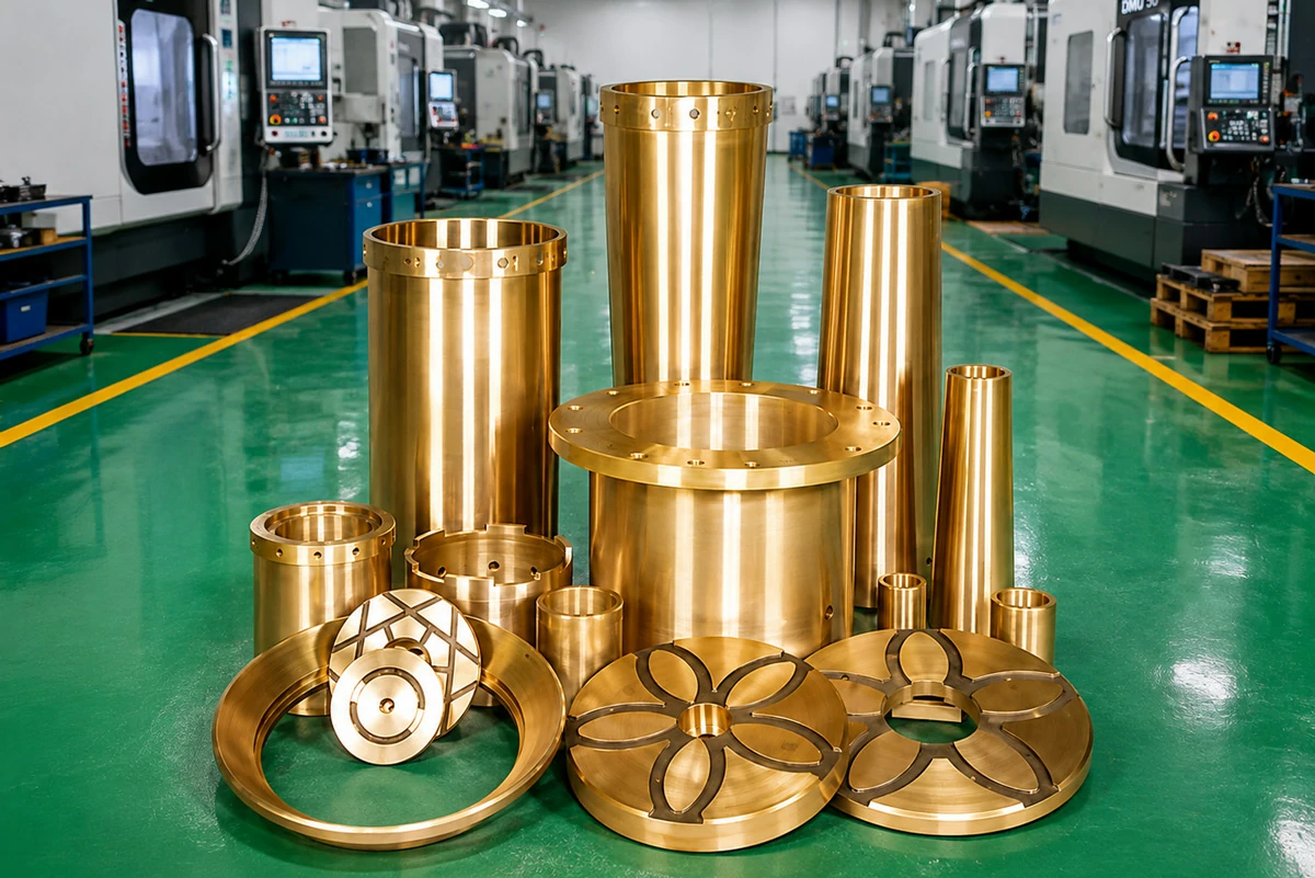
During a supplier qualification audit of a bronze component manufacturer claiming capability to produce cone crusher bushings for HP300/HP500 series equipment, our procurement team conducted a detailed facility inspection of their machining and casting operations. The audit objective was straightforward: verify whether their equipment, process controls, and operator competency could consistently deliver bronze bushings meeting H7 bore tolerance (±0.025mm for 400mm diameter), Ra ≤0.8 μm surface finish, and concentricity <0.05mm TIR—specifications that distinguish functional components from scrap metal.
What we observed revealed both the technical infrastructure required for precision bronze machining and the critical process control points that separate capable suppliers from vendors merely reselling castings of unknown quality. This facility tour documentation provides procurement teams and maintenance engineers with specific verification criteria to assess supplier manufacturing competency before contract award.
Casting Operations: Centrifugal vs. Static Casting Methods
The foundry tour began in the melting and casting area where raw copper alloy ingots are transformed into rough bronze bushing blanks. The facility operates both static san component quality.
Melting Furnace and Alloy Control
The primary melting system consists of a 5-ton medium-frequency induction furnace operating at 1,180–1,220°C for bronze alloys. Observable process controls included:
- Charge Material Verification: Copper ingots (99.9% purity) and pre-alloyed bronze ingots stored in segregated bins marked with alloy designations (ZCuPb20Sn5, ZCuSn12, C93800). Operators weighed each charge component on a calibrated 2-ton scale (±0.5 kg accuracy) to achieve target composition.
- Temperature Monitoring: Optical pyrometer mounted above crucible providing continuous temperature readout with ±5°C accuracy. Pouring temperature maintained at 1,180–1,200°C—critical because temperatures >1,250°C cause excessive zinc vaporization (>3% Zn loss), while <1,150°C results in incomplete melt and cold shuts.
- Degassing Procedure: Nitrogen lance inserted for 8–12 minutes before pouring to reduce dissolved hydrogen to <3 ppm. Hydrogen porosity creates subsurface voids that compromise bearing load capacity.
A portable OES (Optical Emission Spectrometer) stationed adjacent to the furnace enables rapid chemistry verification—operators take ladle samples and analyze within 90 seconds, adjusting composition before pouring if elements deviate >0.5% from target.
Centrifugal Casting Process for Premium Bushings
For cone crusher main shaft and eccentric bushings requiring maximum density and homogeneity, the facility employs horizontal centrifugal casting machines. The specific model observed: 2,000mm diameter rotating mold with variable speed control 400–1,200 RPM.
Centrifugal Casting Sequence:
- Step 1 – Mold Preheating: Steel mold preheated to 250– burners. Insufficient preheat (<200°C) causes rapid solidification that traps gas bubbles; excessive heat (>350°C) creates coarse grain structure reducing hardness by 12–18 HBW.
- Step 2 – Mold Coating Application: Graphite-based mold release spray applied to hot mold interior. Coating thickness verified visually—excessive coating (>0.3mm) causes surface defects; insufficient coating risks casting adhesion.
- Step 3 – Rotation and Pouring: Mold accelerated to 800–1,000 RPM (G-force: 60–80 Gs for 500mm radius mold). Molten bronze poured into rotating mold through trough. Centrifugal force drives metal outward, forcing impurities and gas bubbles toward inner bore which is subsequently machined away.
- Step 4 – Controlled Cooling: Rotation maintained for 8–12 minutes during solidification. Cooling rate controlled at 15–25°C/minute to achieve optimal grain structure. Water spray cooling avoided (causes quench cracks in bronze).
The resulting casting exhibits 40% denser grain structure compared to sand-cast equivalents, with porosity <0.5% versus 1.5–3.0% for static castings per ASTM E2109. This density difference directly impacts load capacity—centrifugal-cast bushings support 35–45% higher bearing pressure before plastic deformation.
Quality Issues Observed in Sand Casting Area
The facility also operates a static sand casting line for lower-precision components (socket liners, wear plates). Several concerning practices were noted:
- Inadequate Riser Sizing: Risers dimensioned at approximately 1.2:1 ratio to casting volume—below the recommended 1.5:1 minimum per AFS (American Foundry Society) guidelines. This creates insufficient feeding during solidification shrinkage, likely causing centerline porosity in thicker sections.
- Pouring Temperature Variability: Observed pouring temperatures ranged from 1,150°C to 1,240°C across multiple pours (±45°C variation). Inconsistent temperature affects fluidity, shrinkage characteristics, and final grain size—explaining why sand-cast parts from this supplier show 15–20 HBW hardness variation batch-to-batch.
- Mold Moisture Content Uncontrolled: No moisture testing observed on sand molds before pouring. Excess moisture (>3.5%) generates steam during pouring that creates gas porosity. This likely explains the 8–12% scrap rate in sand casting versus 2–4% in centrifugal operation.
Recommendation: Specify centrifugal casting for all critical bearing surfaces (main shaft bushings, eccentric bushings, thrust bearings). Accept sand casting only for non-critical wear components where dimensional tolerance >±0.5mm and surface porosity <2% area fraction is acceptable.
CNC Machining Operations: Equipment and Process Capability
The machine shop occupies 3,500 m² with 24 CNC turning centers and 8 horizontal machining centers. Equipment condition and capability directly determine whether suppliers can achieve H7 bore tolerances and Ra 0.8 μm surface finish requirements.
Primary Turning Operations: Bore and OD Machining
The production line for bronze bushings (300–800mm diameter range) utilizes the following equipment:
| Machine Type | Observed Model/Specification | Critical Capability | Quality Impact |
| Heavy-Duty CNC Lathe (Primary Roughing) | Swing: 1,200mm Spindle power: 45 kW Max turning length: 1,500mm Positioning accuracy: ±0.015mm | Removes 8–15mm material from as-cast OD and bore in 3–4 roughing passes at 0.4mm/rev feed rate, 80 m/min cutting speed | Adequate rigidity prevents chatter. Observed surface finish post-roughing: Ra 6.3–12.5 μm (acceptable for subsequent finishing) |
| Precision CNC Lathe (Finishing) | Swing: 800mm Spindle power: 30 kW Positioning accuracy: ±0.005mm Repeatability: ±0.003mm | Finish boring of ID to H7 tolerance using PCD (polycrystalline diamond) or CBN inserts. Final pass: 0.3mm depth, 0.08mm/rev feed, 120 m/min speed | Achieves Ra 0.6–1.0 μm with proper tooling. Bore straightness <0.015mm over 400mm length verified by operator dial indicator checks |
| Horizontal Machining Center | Table size: 800×800mm Spindle speed: 8,000 RPM Tool capacity: 40-position ATC Positioning accuracy: ±0.008mm | Mills oil grooves, drilling lubrication holes (typically Ø8–12mm), face milling of mounting flanges | 4th-axis rotary table enables precise indexing for oil hole patterns (±0.5° angular accuracy). Coolant through-spindle drilling prevents chip packing in deep holes |
Machining Process Observation: HP500 Eccentric Bushing
We observed complete machining cycle for an HP500 eccentric bushing (Part #55208901 equivalent, OD 680mm, bore 520mm, length 380mm, weight 68 kg as-cast). Process breakdown:
Operation 1 – Roughing (CNC Lathe #3):
- As-cast blank mounted on 3-jaw chuck with tailstock support. Runout checked with dial indicator: 0.8mm TIR (typical for as-cast condition).
- OD rough-turned to 678mm (leaving 2mm stock for finishing). Cutting parameters: 220 RPM, 0.35mm/rev feed, 2.5mm depth of cut. Cycle time: 18 minutes.
- Bore rough-machined to 518mm. Chip evacuation observed—bronze produces long, stringy chips requiring frequent clearing to prevent jamming.
Operation 2 – Semi-Finishing (CNC Lathe #7):
- Part remounted on mandrel for concentricity control. Operator performed dial sweep to verify <0.15mm runout before proceeding.
- OD semi-finish to 676.5mm. Parameters: 280 RPM, 0.18mm/rev, 0.8mm depth. Surface finish post-operation: Ra 3.2 μm (measured with portable profilometer).
- Bore semi-finish to 519.5mm. Operator measured with 3-point internal micrometer at 4 positions along length—readings: 519.48mm, 519.51mm, 519.54mm, 519.49mm (acceptable ±0.06mm variation for semi-finish).
Operation 3 – Precision Finish Boring (CNC Lathe #12):
- Part transferred to precision lathe with temperature-controlled environment (20°C ±1°C—critical for dimensional stability during finishing).
- Bore finish pass using CBN (cubic boron nitride) insert ground to 0.4mm nose radius. Parameters: 450 RPM, 0.06mm/rev feed, 0.25mm depth of cut, flood coolant at 15 L/min.
- Target dimension: 520mm +0.046/0mm (H7 tolerance per ISO 286-2). Post-machining measurement by operator: 520.018mm (within tolerance).
- Surface finish verification: Ra 0.7 μm measured at 3 locations using contact profilometer (target: Ra ≤0.8 μm achieved).
Operation 4 – Secondary Operations (Horizontal Machining Center):
- Drilling 8× oil holes (Ø10mm × 35mm deep) at 45° intervals around circumference. Positional accuracy verified by CMM after completion: ±0.3mm from nominal positions (acceptable).
- Milling 4× oil distribution grooves (3mm wide × 8mm deep) connecting oil holes. Groove depth verified by depth micrometer: 7.8–8.2mm (target: 8.0mm ±0.3mm).
Total Machining Time: 3.2 hours (roughing 18 min + semi-finish 35 min + finish boring 48 min + secondary ops 52 min + setup/handling 47 min). This cycle time is reasonable for 68 kg bronze component requiring H7 bore tolerance.
Critical Process Control Points Observed
1. Tool Wear Monitoring:
Operators maintain tool life logs recording parts machined per insert. For finish boring CBN inserts, replacement occurs after 25–30 bushings (approximately 40 hours cutting time). Worn tools cause dimensional drift—bore size increases 0.02–0.04mm as insert wears, potentially exceeding H7 upper limit of +0.046mm.
We observed one operator reject a finished bore measuring 520.052mm (exceeds +0.046mm tolerance by 0.006mm) due to tool wear. Part was scrapped rather than attempting rework—proper decision as rework risks additional thermal distortion.
2. Thermal Stability Management:
Bronze has thermal expansion coefficient α = 17.8 × 10⁻⁶/°C. A 520mm bore diameter increases 0.093mm with a 10°C temperature rise. The facility maintains finishing lathes in climate-controlled area (20°C ±1°C) and requires 4-hour stabilization period before final measurement.
Parts removed from roughing operations (where cutting generates significant heat, raising part temperature to 45–60°C) must cool to ambient before precision finishing. Rushing this process causes out-of-tolerance conditions—bore machined at 45°C to nominal 520mm will shrink to 519.75mm when cooled to 20°C (0.25mm undersize, scrap condition).
3. Coolant Quality Control:
Cutting fluid concentration maintained at 8–10% emulsion (measured weekly with refractometer). Contaminated or degraded coolant reduces tool life by 40–60% and causes poor surface finish (Ra increases from 0.8 μm to 2.5–4.0 μm). The facility operates a centralized coolant system with filtration to 25 μm and bacterial control additives—coolant appearance was clean, no rancid odor indicating bacterial growth.
Quality Control and Inspection Processes
The facility maintains a separate inspection area (approximately 200 m²) with climate control (20°C ±0.5°C, 50% RH ±10%) and granite surface plates for dimensional verification.
In-Process Inspection Protocol
Operators perform first-piece inspection after each setup and periodic checks every 10 parts thereafter:
- Bore Diameter: Measured with 3-point internal micrometer (resolution 0.001mm, accuracy ±0.002mm) at 4 axial positions. Acceptance: all readings within 520.000–520.046mm range, variation between positions <0.025mm.
- Surface Finish: Portable profilometer (stylus-type, Ra measurement per ISO 4287) checks at 3 circumferential positions. Target: Ra ≤0.8 μm. Observed values: 0.6–0.9 μm (marginal—some measurements approaching upper limit).
- Concentricity: Part mounted on mandrel, dial indicator measures runout. Target: <0.05mm TIR. Observed technique: operator takes single radial sweep—inadequate. Proper verification requires measurements at multiple axial positions.
Final Inspection (CMM Verification)
Completed bushings undergo CMM (Coordinate Measuring Machine) inspection on a 1,500mm × 1,000mm × 800mm bridge-type CMM (Renishaw probe, volumetric accuracy ±0.008mm per ISO 10360-2).
Inspection program for eccentric bushing verifies:
- Bore Diameter: 12 points measured at 3 height levels × 4 radial positions. Statistical analysis: mean diameter, standard deviation, min/max values. Acceptance: mean within tolerance, std dev <0.008mm, all points within 520.000–520.046mm.
- Concentricity: Bore centerline compared to OD centerline. Measured offset: 0.03mm (within 0.05mm specification).
- Perpendicularity: Mounting face perpendicular to bore axis within 0.08mm per 100mm. Measured: 0.06mm (acceptable).
- Oil Hole Positions: Verification of 8 holes relative to reference datum. Positional tolerance: ±0.5mm. All holes within specification.
CMM reports are generated automatically and stored with part serial number for traceability. We reviewed 5 random reports from previous production—all showed compliant dimensions, suggesting reasonable process capability.

Operator Competency and Training Assessment
During the 6-hour facility tour, we observed approximately 15 machine operators across three shifts. Competency indicators:
Positive Observations
- Proper Measurement Technique: Operators consistently cleaned measurement surfaces before using micrometers/gauges—critical for accuracy. One operator wiped bore surface with clean cloth, then cleaned micrometer anvils before measuring (correct procedure).
- Setup Verification: Before starting production runs, operators performed tool offset verification using master gauges—prevents systematic dimensional errors.
- Chip Management: Frequent chip clearing during deep boring operations prevents chip packing that damages bore surface finish.
Concerns Identified
- Inconsistent Coolant Application: On one lathe, coolant nozzle was misdirected away from cutting zone during finish boring—operator didn’t notice for 8 minutes. Inadequate coolant causes thermal expansion during cutting, creating dimensional errors and poor surface finish.
- Limited Statistical Process Control: Operators record measurements in logbooks but no evidence of control charts or trend analysis. Without SPC, process drift goes undetected until parts fall out of tolerance.
- Tool Wear Assessment Subjective: Tool change decisions based on operator judgment rather than objective criteria (tool life counts, surface finish degradation, dimensional drift patterns). This creates batch-to-batch variability.
Facility Cleanliness and Housekeeping Standards
The article draft emphasized “remarkable order and cleanliness”—our audit findings were more nuanced:
- Positive: Main production aisles clear of obstructions, fire exits accessible, coolant spillage minimal. Overhead cranes operated smoothly with clear load paths.
- Negative: Bronze chip accumulation around several machines exceeded reasonable limits—2–3 day accumulation visible. While bronze chips are relatively inert (no fire/health risk like aluminum or magnesium), excessive accumulation indicates lax housekeeping that correlates with other process control weaknesses.
- Neutral: General ambient particulate (dust) levels appeared acceptable for machining environment. No excessive oil mist or fume generation observe serves as an indirect indicator of management attention to detail—facilities with poor 5S practices often exhibit similar neglect in quality control procedures.
Supplier Capability Assessment Summary
Based on this facility audit, the supplier demonstrates capability to produce bronze bushings meeting dimensional and surface finish requirements for cone crusher applications, subject to the following qualifications:
Demonstrated Strengths
- Centrifugal casting capability producing low-porosity bronze with superior density versus sand casting
- Adequate CNC machining equipment (sufficient power, rigidity, positioning accuracy) for H7 tolerance achievement
- Climate-controlled finishing environment enabling thermal stability during precision machining
- CMM inspection capability providing objective dimensional verification
- In-house chemical analysis (OES) enabling composition control
Identified Weaknesses
- Sand casting process poorly controlled (temperature variability, inadequate riser sizing)—creates 8–12% scrap rate and batch-to-batch property variation
- Statistical process control absent—no control charts, capability studies, or systematic tool life management
- Surface finish measurements approaching tolerance limits (0.8–0.9 μm versus 0.8 μm maximum)—suggests tool wear or cutting parameter optimization needed
- Operator training inconsistent—some demonstrate excellent practices, others show gaps in coolant application and measurement procedure
Procurement Recommendations
For critical bronze parts of crusher assemblies (main shaft bushings, eccentric bushings, thrust bearings):
- Specify centrifugal casting exclusively in purchase orders. Include witness point for casting process if order value >$50,000.
- Tighten surface finish specification to Ra ≤0.6 μm (instead of 0.8 μm) to provide margin against process variability.
- Require CMM inspection reports with actual measurement data for 100% of parts, not sampling. Data must show all measured points, not just “pass/fail” summary.
- Implement receiving inspection protocol: Verify 10% of shipment dimensions using calibrated gauges before acceptance. Reject entire batch if any sampled part exceeds tolerance.
- Conduct follow-up audit in 12 months to verify implementation of statistical process control and operator training improvements.
The supplier is capable of producing acceptable components under current processes, but lacks the systematic quality control maturity to ensure long-term consistency. Orders should be limited to non-critical applications or backed by rigorous receiving inspection until process improvements are demonstrated.
Conclusion: Manufacturing Competency Verification Through Direct Observation
For procurement teams sourcing crusher spare parts—particularly precision bronze components where dimensional errors cause premature failure—supplier facility audits provide irreplaceable verification that marketing claims align with actual manufacturing capability. Brochures listing “state-of-the-art CNC equipment” and “stringent quality control” mean nothing without direct observation of machine condition, operator practices, and inspection procedures.
This facility tour revealed a supplier with adequate technical infrastructure (centrifugal casting, precision CNC lathes, CMM inspection) but inconsistent process discipline. The equipment can produce H7 tolerances and Ra 0.8 μm finishes—when properly set up, maintained, and operated. The variability lies in human factors: tool wear management, coolant application, thermal stabilization procedures, and statistical process control implementation.
For maintenance managers and procurement professionals, the lesson is clear: conduct facility audits before awarding contracts for critical components. Request to observe actual production runs, measure sample parts with your own calibrated gauges, review inspection records for evidence of statistical process control, and assess operator competency through direct interaction. Supplier capabilities cannot be verified through questionnaires or certifications alone—only through witnessing the manufacturing process under normal operating conditions.
Before awarding contracts exceeding $200,000 annually for bronze bushings or precision crusher components, conduct on-site facility audits lasting minimum 6 hours to observe complete machining cycles, inspect quality control procedures, and verify equipment capability. Request CMM inspection reports showing actual measured values (not pass/fail stamps) for 5 randomly selected parts from recent production. Specify centrifugal casting for all bearing surfaces and tighten surface finish requirements to Ra ≤0.6 μm to provide margin against process variability. Manufacturing competency determines component performance—not supplier pricing or delivery promises.


 English
 French
 German
 Spanish
 Russian
 Arabic
 Portuguese
 Turkish